Whether to have an AC Reactor or a DC Link Choke for Your VFD?
Reactor an Introduction.
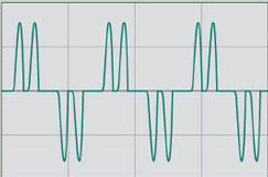
A reactor designed for Variable Frequency Drives (VFD’s) is typically nothing more than a coil of wire wrapped around a laminated steel core. The characteristic of the reactor that we desire is inductance, “the opposition to a rapid change in current flow”. VFD’s draw current from the power line in sharp pulses, causing harmonic current to flow. The current is drawn in sharp pulses because the input diodes only conduct current at the peak of the voltage waveform to keep the capacitors fully charged.
Typical VFD Line Current: No Reactor
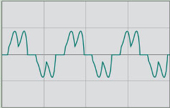
It is this feature that allows reactors to smooth the current flow to VFDs and reduce harmonics.
Additionally, smoothing the current flow limits the high peak current pulses from abusing the capacitor bank inside the VFD. Thereby extending the life span of the drive and improving the drive’s True Power Factor.
Reactors for VFDs are sold as either AC reactors or DC reactors (also called DC link chokes). Both reactor types serve the same
Typical VFD Line Current: 3% Reactor
 primary purpose, to smooth the current flow to the VFD, and reduce damaging harmonics produced on the power line. However, there are advantages and disadvantages to both AC & DC reactors.
AC Reactors. AC reactors are placed in series with the incoming AC power line. An advantage they provide is some protection from voltage transients created by power factor capacitor switching and voltage spikes/lightning surges because they are installed before the VFD. A disadvantage they cause is a voltage drop to the VFD due to a condition called Overlap of Diode Conduction.This can be a problem when the VFD is installed on a power line that dips in voltage. If the voltage dips low, and the AC reactor drops some voltage, the drive might nuisance trip on an Under Voltage or Power Loss fault trip. For example 5% impedance rated AC reactor could drop a 460VAC line, down to 437VAC into the VFD. This could potentially nuisance fault trip the VFD. Finally, AC reactors are generally 1.5 more expensive than DC reactors for the same impedance.
 DC Link Chokes. DC reactors (link chokes) are connected after the input diodes in the power circuit. A disadvantage to DC reactors is they are located after the input diodes, and do not protect the diodes from possible voltage transients. Because only one coil is needed in a DC circuit vs. 3 coils in AC, DC reactors are less expensive. By locating the reactor in the DC Link, we do not have the Overlap of Diode Conduction. Therefore, these reactors do not drop voltage to the drive, avoiding the nuisance faults.
WHICH ONE SHOULD YOU HAVE?
When shopping for a reactor we generally look to see how much the reactor will reduce the damaging harmonics. A VFD with no reactor could produce 60-130% harmonic current distortion on the power line.
Reactors are commonly sold in values of percent impedance with 1.5%, 3%, and 5% being standard values sold. Ideally, 5%-6% overall impedance will yield the best cost vs. effect. Installing one with greater than 6-7% impedance has little beneficial effect on harmonic reduction with a major disadvantage of excessive losses. That leaves the question do we install an AC or DC reactor?
HAVE BOTH!
The best solution to balance the advantages and disadvantages of AC & DC reactors is to install both! A 3% DC and 3% AC reactor solves all the problems, and has very few drawbacks. The 3% AC reactor will protect the diodes against voltage transients, but not drop excessive input voltage to cause nuisance fault trips. The DC reactor provides the ideal 3% impedance with no voltage loss due to diode overlap conduction at a lower cost.
By incorporating both AC & DC reactors in your VFD application 6% impedance is achieved, the best cost vs. effect is achieved, harmonics are greatly reduced, and all the reactor advantages are gained with little disadvantage.

