Brosea Electric Limited
Tel: +86-755-23060870
Fax: +86-755-33671802-8002
Email: info@brosea.com
How Soft Starters for Induction Motors Work
Soft Starters for Induction Motors
A soft starter is another form of reduced voltage starter for A.C. induction motors. The soft starter is similar to a primary resistance or primary reactance starter in that it is in series with the supply to the motor. (Three wire or standard connection) The current into the starter equals the current out. The soft starter employs solid state devices to control the current flow and therefore the voltage applied to the motor. In theory, soft starters can be connected in series with the line voltage applied to the motor, or can be connected inside the delta loop of a delta connected motor, controlling the voltage applied to each winding. (Six wire or Inside Delta connection)
Voltage Control
Voltage control is achieved by means of solid state A.C. switches in series with one or more phases. These switches comprise either:
| 1 x Triac per phase | |
| 1 x SCR and 1 x Diode reverse parallel connected per phase. |  |
| 2 x SCRs reverse parallel connected per phase. |  |
Solid state switches
These Solid State Switches are phase controlled in a similar manner to a light dimmer, in that they are turned on for a part of each cycle. The average voltage is controlled by varying the conduction angle of the switches. Increasing the conduction angle will increase the average output voltage. Controlling the average output voltage by means of solid state switches has a number of advantages, one of the major advantages being the vast improvement in efficiency relative to the primary resistance starter, due to the low on state voltage of the solid state switches. Typically, the power dissipation in the starter, during start, will be less than 1% of the power dissipated in a primary resistance starter during start. Another major advantage of the solid state starter is that the average voltage can be easily altered to suit the required starting conditions. By variation of the conduction angle, the output voltage can be increased or reduced, and this can be achieved automatically by the control electronics. The control electronics can be preprogrammed to provide a particular output voltage contour based on a timed sequence (open loop), or can dynamically control the output voltage to achieve an output profile based on measurements made of such characteristics as current and speed (closed loop).
Switching Elements.
The switching elements must be able to control the current applied to the motor at line voltage. In order to maintain a high level of reliability on a real industrial type supply, the switching elements need to be rated at least 3 times the line voltage. On a 400 volt supply, this means that the requirement is for 1200 Volt devices, and 600 Volt devices on a 200 volt supply. It is also important that the switching elements have a good transient current overload capacity.
1200 Volt triacs with good current transient overload characteristics are not readily available, and so the choice is really between the SCR-Diode and SCR-SCR. There are some triacs which are suitable for this operation, but they are not easily attainable.
The major differences between the SCR-SCR and the SCR-Diode options are price, and the harmonic content of the output voltage. The SCR-SCR method provides a symmetrical output which is technically desirable from the point of supply disturbances and harmonics, while the SCR-Diode method is inferior technically, it is commercially more effective and easier to implement.
Harmonics awareness and paranoia has drastically reduced the number of SCR-Diode type soft starters on today's market, but they do still exist. The technology is not always easily recognizable as such with terms such as three pulse technology being used to describe SCR-Diode systems as opposed to six pulse technology describing SCR-SCR systems.
The soft starter can be designed to control one phase, reducing the torque but not the current on two phases, (SCR/Diode can not be used in this connection)
or two phases reducing the torque but the current will not be optimally reduced or balanced, there will be negative sequence currents heating the rotor and reducing the torque per unit start current, (SCR/Diode can not be used in this connection)
or three phases, reducing current and torque, providing the optimum results for torque generated per unit of start current.
Bypass Contactors
The SCRs used in soft starters dissipate heat while the starter is running because there is current through the SCRs and a voltage drop across them. Typically, the power dissipation is not high as there is usually only 1 - 1.5 volts across the ON state SCRs.
As ameans of reducing the heat dissipated, bypass contactors are connected across the SCRsshorting them out while the starter is running. These contactors are usually AC1 rated and are either internal or external.
It is important that the bypass contactors to not short out the current transformers as well.
Open Loop Control.
Open Loop soft starters are soft starters producing a start voltage profile which is independent of the current drawn, or the speed of the motor. The start voltage profileis programmed to follow a predetermined contour against time. A very basic Timed Voltage Ramp (TVR) system operates by applying an initial voltage to the motor, and causing this voltage to slowly ramp up to full voltage. On basic systems, the initial start voltage is not adjustable, but the ramp time is. Commonly the voltage ramps time is referred to as the acceleration ramp time and is calibrated in seconds. This is not an accurate description as it does not directly control the acceleration of the motor. A lightly loaded motor can accelerate to full speed even with a sixty second ramp selected. More correctly this should be referred to as the voltage ramp time. On more comprehensive units, the start voltage is pre-setable, typically from 10% to 70% of full line voltage. This should be set to achieve at least breakaway torque for the motor at start. There is little advantage in the motor sitting, staining to start due to insufficient torque. this will only increase the heat dissipated in the motor. The start voltage setting is often referred to as the start torque setting and calibrated in percent. This is a nonsense, as although increasing the start voltage is going to increase the starting torque of the connected motor, the actual starting torque is a function of both the start voltage and the motor design. The starter does not know anything about the connected motor, and so is not able to deliver a prescribed amount of torque under open loop conditions. The actual start torque produced is initially equal to the LRT multiplied by the square of: (the start voltage divided by the line voltage). The LRT of the motor could vary from as low as 60% FLT to as high as 350% FLT which is a range of almost 6 to 1.
The start voltage profile
The Start Profile can be a simple single slope from zero voltage to full voltage, or it can be a complex shape to more closely emulate a controlled current start.
Like electromechanical starters, open loop soft starters cause the start voltage applied to the motor, to change with time irrespective of the motor and load conditions, eventually getting to full voltage, and under jammed load conditions, developing LRC and LRT until something trips or breaks.
Closed Loop Control.
Closed Loop starters monitor an output characteristic or effect from the starting action and dynamically modify the start voltage profile to cause the desired response. The most common closed loop soft starter is the controlled current soft starter where the current drawn by the motor during start is monitored and controlled to give either a constant current, or a current ramp soft start. A much rarer closed loop format is the constant acceleration soft start where the motor speed is monitored by a tachogenerator or shaft encoder and the voltage is controlled to maintain a constant rate of acceleration or a linear increase in motor speed.
The controlled current soft starters are available with varying levels of sophistication. In the most basic systems, the soft starter is essentially a standard TVR soft starter with a ramp freeze option where the current on one phase is monitored and compared to a set point. If the current exceeds the set point, the ramp is frozen until the current drops below that set point. At the other end of the scale, a comprehensive closed loop soft starter will monitor the current on all three phases and dynamically change the output voltage to correct the start current to the required profile. This system is able to both increase and reduce the start voltage to suit the application.
A constant current starter will start initially at zero volts and rapidly increase the output voltage until the required current is delivered to the motor, and then adjust the output voltage while the motor is starting until either full voltage is reached, or the motor overload protection operates. Constant current starters are ideal for high inertia loads, or loads where the starting torque requirements do not alter.
The current ramp soft starter operates in the same manner as the constant current soft starter except that the current is ramped from an initial start current to a current limit setting over a period of time. The initial start current, current limit, and the ramp time are all user adjustable settings and should be customize to suit the application. The current ramp soft starter can be used for a number of advantages over constant current in some applications. Machines which have a varying start torque requirement, such as on load conveyers, or applications requiring a reduced initial torque such as pumping applications, or genset applications where the relatively slow application of current load will allow the genset to track the load are examples of situation where the current ramp soft start can be used to advantage.
Another form of closed loop starter is the torque control starter where the starter models the motor under high slip and low slip conditions and uses this mathematical model to calculate the shaft torque being produced by the motor. This is then used as a feed back source with linear and square law start torque curves being used to control the start voltage applied to the motor. The true torque control starter is able to give much better control of the acceleration of the motor being started.
Starting Torque
To start a machine, the motor must develop sufficient torque over the entire speed range to exceed the work and loss torque of the driven load, and provide a surplus torque for accelerating the machine to full speed. The starting torque delivered by the motor at any speed, is equal to the full voltage starting torque at that speed, multiplied by the current or voltage reduction squared. Provided the full voltage speed/torque curves and the full voltage speed/current curves are available, the reduced voltage (or current) speed/torque curves can be calculated. This curve can be superimposed onto the load speed torque curve, and provided the torque developed at all speeds exceeds the load torque, the motor will accelerate to full speed. If the curves cross, the start current (or voltage) will need to be increased to increase the start torque developed by the motor. The difference between the torque developed and the load torque is essentially the acceleration torque that will accelerate the machine to full speed. A high acceleration torque may be desirable for a high inertia machine in order to minimize the starting time.
With a controlled current soft starter, the voltage reduction reduces as the motor impedance accelerates due to the rising motor impedance. As the motor approaches full speed, the voltage rises quickly (against speed) to full voltage. When the torque curve for a motor started by a constant current starter is compared with that of a constant voltage starter such as an auto transformer starter, it can be seen that there is an increase in the torque as the motor accelerates with a constant current start. This is ideal because as the motor and machine increase in speed, the actual load on the motor shaft will increase also. This characteristic will often enable a load to be started with a lower current on a soft starter than traditional starter methods.
Soft Stop.
Soft starters can have soft stop included for no extra cost.
Soft stop is the oposite to soft start. The voltage is gradually reduced, reducing the torque capacity of the motor. The reduction of available torque causes the motor to begin to stall when the shaft torque of the motor is less than the torque that is required by the load. As the torque is reduced, the speed of the load will reduce to the point where the load torque equals the shaft torque.
Typically, the soft stop used is an open loop voltage ramp, but there are some torque control soft stop systems that use torque feedback to provide better control over the deceleration of the motor.
Open loop soft stop performance is very dependent on the characterisitcs of the motor and driven load. On larger machines this can be very non linear and provide poor performance.
Soft stope effectively adds inertia to the load and extends the braking time. It should only be applied to installations where the stopping time is too short and needs to be extended. Soft stop does not provide any measure of braking.
DC Brake
DC Braking can be added to soft starters, but the effectiveness is not as good as the braking that can be achieved with a specialist DC brake circuit. DC braking is achieved by turning ON a positive SCR on one phase and a negative SCR on a second phase for a small angle of each cycle. This causes a high pulse of DC current to flow through the motor windings and creates a stationary torque field in the stator. The stationary torque field causes the motor to slow down. The short pulses at line frequency also produce a synchronous component in the torque field that can limit the effectiveness at close to synchronous speed. In some cases, a shorting contactor is connected across a motor winding to prolong the period of current flow and reduce the line frequency component.
DC braking is used to apply a braking torque to the motor and load and to make it stop quicker. During DC braking, the energy of the driven load is dissipated in the rotor of the motor.
Slip Ring Motors.
Soft starters can be applied to many slip ring motors, however there are some where the application of a soft starter will not give satisfactory results.
Slip ring motors are often employed for their ability to produce a very high torque across the entire speed range. The slip ring motor is able to do this at a very low start current. Another reason for the application of a slip ring motor is that it is able to offer a high degree of control.
If the slip ring motor is employed to give a very high start torque across the entire speed range, then the soft starter is not going to provide a satisfactory solution. This is because the application of a soft starter or any other primary starter, is going to reduce the torque available. Where the requirement is for a gentle start at reduced torque, the soft starter is of benefit.
A common misconception is that the slip ring starter can be converted to a cage type motor by shorting the slip rings and starting by the normal methods. If the secondary winding is shorted, the slip ring motor will exhibit a very high LRC (typically >1000%) and a very low LRT (typically < 100%). If a reduced voltage starter is applied under these conditions, the start torque will be very low and will not start a machine. To apply a reduced voltage starter to a slip ring motor, first ascertain that a reduced torque is going to start the machine, then fit resistors to the rotor circuit which will give curves similar to a high start torque cage motor. These resistors must then be bridged once the machine has reached full speed. The value of the resistance is dependent on the motor and the curve required, however the resistors must absorb a lot of energy, dependent on the inertia of the load. It is common to use the final stage resistance of the existing starter when available.
Ratings
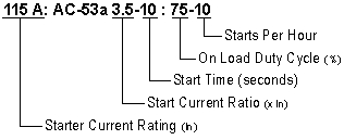
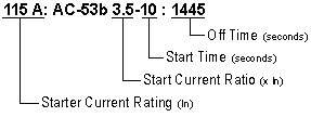
Soft Starter ratings are covered by IEC947-4-2 in much the same way as contactors. There are two utilisation categories for soft starters: AC53a and AC53b. AC53a applies to starters that are not bypassed and AC53b ratings apply to starters that are bypassed during run. AC53a rated starters have current passing through the SCRs all the time that the starter is running. This generates heat and elevates the operating temperature of the SCR junction. AC53b rated starters only pass current through the SCRs during start and the period between starts is effectively a cool down period for the SCRs. This can result in an increased rating in some situations.
As the rating of the starter is essentially thermal, there is a strong relationship between the start time, start current, start frequency, ambient temperature, OFF time, and the rating of the starter. Typically, there thermal inertia of the SCR Heatsink assembly is quite long so there is not a large variation in the rating between say a 10 second rating and a 30 second rating. - Semiconductor fuse curves do not follow the ratings curves for soft starters and only offer Short Circuit protection.